01 March 2012

Engine Reassembly #1

Now that the crankcase halves are painted it's time to start reassembling the engine.  One nice thing about this process is that I can do it in the basement at all hours of the night without worrying about waking up the neighbors.

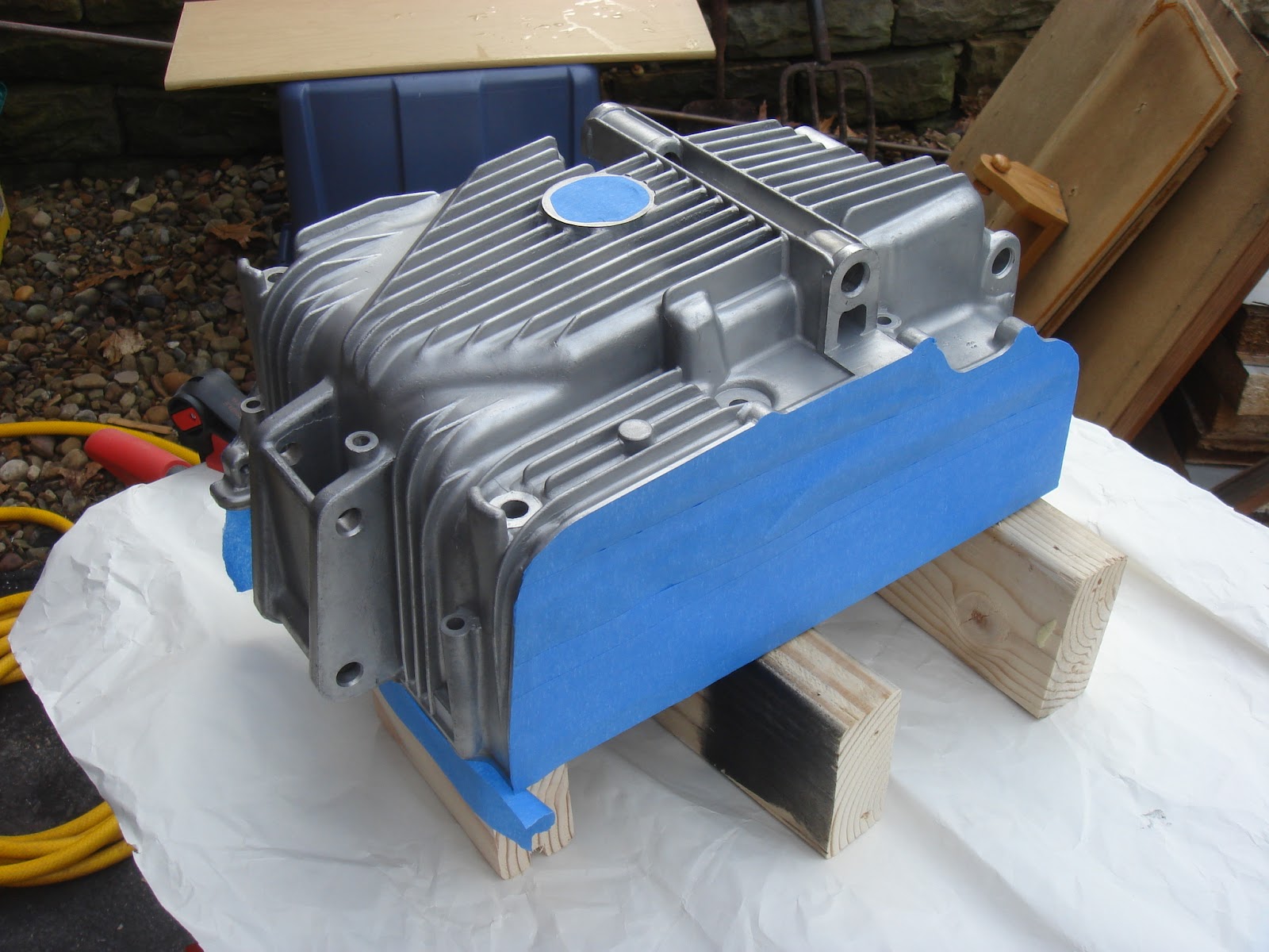
Clean and ready to go.

The oil separator went in first.  I used blue Loktite on the screws because
some of them were really short and the last thing I want is one of them
vibrating loose.

The kickstart assembly went in next and that was it for the bottom half.

My little makeshift engine stand has really come in handy lately.

Gearshift forks went in first.

And then the camshaft.

All of the oil seals have been replaced with OEM seals from BikeBandit.com

The transmission with new oil seals in place.

Don't worry, I didn't forget the cam chain.  The next step will be to seal the
upper and lower halves together and crack on with the rest of the assembly.

Rearset Mounts

I've been on the fence for quite a while as to how I wanted to mount the rearsets.  I've seen a ton of bikes that just used the passenger peg mounts in one way or another so that was the first way I mocked it up but it just didn't feel right.  It also lead to some other issues like where to mount a stopper for the right rearset so that brake linkage didn't pull it out of position.  Making custom mounts seemed to be the only solution to get the result I was looking for.

Getting ready to remove the passenger foot peg mounts.

Now the hard part begins; grinding away all of the extra metal and welds.

I cut the new mounting points for the rearsets out of 1/4" steel plate.

Another view of the mounting points with the spacers removed.

Here is a look at the wood mockup I made for the rearset mounts and the
finished "blanks" for the steel rearset mounts.  I made these out of the same
1/4" steel plate as the mounting points.

I used a paper template as a guide for the hole placement.

The holes were enlarged with a step bit from both sides to create clean,
chamfered  holes.

Stainless hardware from BoltDepot.com

A perfect fit thanks to many, many paper and wood mockups.

This setup will be much more comfortable (at least for me) than using the
passenger peg mounts as I've seen done on so many other bikes.

22 February 2012

The Crankcase #2

We finally got a warm(ish) day where it wasn't raining so I decided to take advantage of it and paint the crankcase halves.  In anticipation of nicer weather this week I had been prepping everything and making sure I had the necessary supplies on hand.  I had cleaned the case halves previously but they had a lot of WD-40 on them so the first step of the day was to degrease them.

Soaking in a coat of degreaser.

Masking is one of my least favorite parts.

Primed and ready for paint.

Both halves masked and primed.

Three light coats of paint.  I pleasantry surprised at how close the paint
color resembles bare cast aluminum.

Drying in the safety of the garage.  I moved them into the basement after
letting them air out for a few hours so they can continue to dry in a
constant temperature.

The Crankcase #1

I'm not sure what this piece is actually called but for the sake of this post I'm going to call it the oil separator plate.  It was originally mounted in the lower half of the crankcase with two screws in the center holes and basically riveted to the crankcase in the corners.  To remove it I had to grind down the "rivets" in the corners with a Dremel.  Easy enough to remove, but I was left with the task of remounting it for the rebuild.  I was tempted to just use the two screws in the center holes and some Loctite to make sure they didn't come loose but I was afraid that the engine vibration might make the loose corners vibrate.  The last thing I want to do after rebuilding the engine is to tear is back down to fix a rattle.  The best solution I could come up with was to drill and tap the corner mounts and use screws in all six holes.

Here is what the mounting points looked like after grinding down the corners
to remove the oil separator plate.

Another view of the mounting points in the lower crankcase.

Getting lined up to drill the first hole.

I didn't dare go down more then 5/8" because I didn't want to
risk punching through underneath.

One down, three to go.

Here is a shot of the plate mounted.

28 January 2012

Building the Seat Plug #3

After the issues I had with painters tape and foam I took a different
approach.  I used electrical tape to protect the edges that I didn't want foam
to adhere to and then used gorilla tape without the painters tape under it.
I only used painters tape for the sections that foam most likely wouldn't reach.

Another view of the taped up plug before pouring.

Building the Tank Plug #4

The remaining pieces of the plug skeleton have been glued and screwed in place.
At this point I began taping up the tunnel to prep for foam.

I used painters tape to protect the wood from the gorilla tape.  By doing it this
way I figured that I could get the strength of the gorilla tape but avoid having
to scrape off the sticky crap it leaves behind when you peal it off.

I covered the bottom with painters tape just in case the foam spilled over too
much.  I also reinforced the tunnel tape with gorilla tape.

Getting ready to pour.

I used red party cups to mix small batches to fill each of the cavities.  The
chemical reaction creates a good deal of heat.

I used a combination of coping saws and brute force to break the excess
foam free.  The painters tape plan back fired a little.  It did make it much
easier to remove the gorilla tape but it wasn't strong enough to tear away
from the foam.

Here's another shot the plug after removing as much tape as I could by hand.

I used an angle grinder to remove the rest of the tape and excess foam.  This
process produces a ton of fine dust that seems to cling to any surface it touches.
I wore a respirator and googles at all times during the grinding and cleanup.

The grinder would fit in the tunnel so I used a Demel MultiMax to cut out
most of the excess foam from.  I have to do the rest by hand with a rasp
and some sanding blocks.

Filling in the tail end of the tank

I used the same process as before for the remaining foam.

Another shot of the plug so far.

18 January 2012

Building the Tank Plug #3

I added some panels to the knee dents to ensure a flat surface.

Some additional pieces were added to the front section as well to help
maintain the desired shape and symmetry through the foam and Bondo process.